
Using Y Connectors in String Inverter Systems: Part I
In Part I of this blog post Eric Every, Yaskawa - Solectria Senior Applications Engineer, explores cases in which PV system designers should use Y-connectors, what the code implications may be, how they may be used with internal inverter combiners. This article originally appeared in the Jul/Aug edition of SolarPro. You can view it here: . Part II of this post is located https://www.solectria.com/blog/using-y-connectors-in-string-inverter-systems-part-ii/.
Y is it?
At Solar Power International last year, a sales representative for one of our distribution partners inquired: “Why do so many of my customers order 30A fuses in their source-circuit combiner boxes?” This is a good question. Fuses rated for 30A assumes an Isc of roughly 18 A, which is an unprecedented series fuse rating for today’s PV modules. The answer is not a function of module ratings per se, but rather of how system integrators deploy these modules. Specifically, more and more installation companies use special Y-connector assemblies to parallel PV source circuits in the array field as a way to optimize electrical balance of system (eBOS) costs.
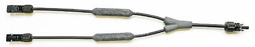
An example of a Y-connector assembly with integral in-line fuses is shown here.
Most industry veterans have seen parallel branch connectors or Y-connector assemblies at conferences or pictured in trade publications or product catalogues. For example, both Multi-Contact and Amphenol offer male and female branch connectors rated for 30 A, as well as overmolded Y-connector assemblies with optional inline fuses. Many eBOS companies also offer customizable Y-connector assemblies. What these connectors and assemblies all have in common is that they have two inputs and one output, allowing installers to make plug-and-play parallel connections within the array.
Until recently, paralleling source circuits within an array was most common in thin-film applications. Compared to c-Si PV modules, thinfilm technologies tend to have a higher Voc and a lower Isc. As a result, it behooves integrators to use wire harnesses with inline fuses to parallel thin-film PV source circuits prior to landing them in a combiner box. This practice is cost effective because it improves conductor utilization within the array and limits the number of combiner box inputs.
Designers can apply these same principles to c-Si PV arrays. After all, touch-safe fuseholders in combiner or inverter wiring boxes are generally 30 A rated, whereas most PV modules have a 15 A series fuse rating. Therefore, integrators may be able to improve project economics by using Y-connectors to parallel a pair of source circuits ahead of these fuseholders. Before evaluating the potential cost savings associated with this approach, let us review some practical considerations.
Code Considerations
NEC Section 690.9 requires overcurrent protection for PV modules or source circuits, except when there are no external sources of fault current, or the short-circuit currents from these sources do not exceed the ampacity of the conductors and the maximum series fuse rating. To make a parallel connection ahead of a combiner box, designers need to account for potential sources of fault currents as well as the module manufacturer’s series fuse ratings. Generally speaking, Y-connector assemblies with inline fuses are required to make parallel connections within the array. In effect, designers need to relocate 15 A series fuses from the combiner box out into the array wiring.
Since parallel connections increase current, designers also need to evaluate conductor ampacity between the Y-connector and the dc combiner or inverter-input wiring box. To achieve the desired cost savings, integrators need to be able to parallel source circuits within the array without unnecessarily incurring the expense of larger-diameter conductors. To avoid having to step from 10 AWG to 8 AWG copper conductors, for example, designers should avoid or minimize situations that require conductor ampacity adjustments according to Article 310.
Is Your Product 30 A Ready?
While most of the finger-safe fuseholders for 10 mm by 38 mm fuses found in combiner boxes are manufacturer rated for 30 A, the busbars connected to the fuseholders are not always capable of carrying 30 A of current. Integrators should check with the combiner or pv inverter manufacturer to ensure that the product is compatible with the use of 30 A fuses.
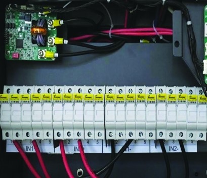
To facilitate cooling and prevent overheating, manufacturers may recommend alternating input conductors, as shown here, so that every other fuseholder has a 30 A fuse and the rest of the inputs are unused, with the fuses removed.
In some cases, equipment manufacturers require an allowance for heat dissipation where fuseholders are fused at 30 A. The concern is that a lack of space between fuseholders can cause a fuseholder to overheat, potentially melting the plastic and causing a fault. This is not an issue when inputs are fused at 15 or 20 A, as is typical of most string inverter or combiner box applications. However, it may become an issue under continuous loading at full power with 30 A fuses and removing the unused fuses is one way to improve heat dissipation.
Part II (https://www.solectria.com/blog/using-y-connectors-in-string-inverter-systems-part-ii/) of this article explores commissioning and maintenance considerations, cost reductions and wraps up with a case study.
In a couple of weeks, Yaskawa - Solectria Solar is exhibiting at Solar Power International 2016 in Las Vegas, NV (Booth #1717). They will show a decentralized system set up utilitzing Y connectors. Make sure you drop by to chat with Eric and the rest of our team!
Questions or comments? Contact:
Eric Every
Sr. Applications Engineer
Yaskawa – Solectria Solar
eric.every@solectria.com
978-771-7598
Natalie Holtgrefe
Head of Marketing
Yaskawa – Solectria Solar
natalie.holtgrefe@solectria.com
781-640-0755
Please email questions and ideas to natalie.holtgrefe@solectria.com.