Using Y Connectors in String Inverter Systems: Part II
In Part II of this article Eric Every, Yaskawa-Solectria Senior Applications Engineer, explores commissioning and maintenance considerations, cost reductions and a case study. This article originally appeared in the Jul/Aug edition of SolarPro. The complete article originally appeared in the Jul/Aug edition of SolarPro. You can view it here: https://solarprofessional.com/articles/design-installation/using-y-connectors-in-string-inverter-systems. You can read Part I of this post here: https://www.solectria.com/blog/using-y-connectors-in-string-inverter-systems-part-i/.
A Small Sacrifice in Convenience…
From a commissioning and maintenance perspective, incorporating Y-connectors into the PV array wiring does somewhat compromise convenience. After all, landing individual source circuits in combiner boxes provides commissioning agents and service technicians with a convenient means of isolating individual circuits, both to validate proper installation and to establish baseline performance parameters. Using Y-connectors pushes some of the parallel connection points into the array, which can complicate some routine maintenance and troubleshooting procedures, such as taking Voc measurements on a single source circuit.
Arrays fielded with Y-connectors may also require specialized diagnostic tools. After array commissioning, source-circuit voltage measurements are less important than I-V curve traces, as the latter provide more insight into array health. To capture I-V curve traces on source circuits paralleled using a Y-connector, service technicians must have access to an I-V curve tracer rated to process the combined short-circuit current of both strings. At present, the Solmetric PVA-1000S is the only handheld I-V curve tracer offered with an optional 30 A measurement capability. With this 30 A–rated PV Analyzer, technicians can perform an I-V curve trace in a combiner box on two paralleled c-Si PV source circuits. If technicians have access to a 15 A–rated I-V curve tracer only, they will need to isolate the source circuits from the Y-connector and trace each I-V curve individually.
…Yields Reduced System Cost
The reason system integrators are willing to make a small sacrifice in convenience is that the proper use of Y-connectors reduces installed system costs. The savings are twofold: material savings associated with a reduction in the total length of PV Wire within the array field, and labor savings, since installers do not have to make as many terminations in source-circuit combiners.
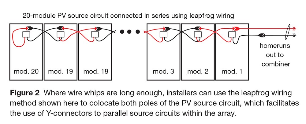
To realize the maximum PV Wire savings, installers need to locate both poles of each PV source circuit at roughly the same spot within the array table. Using the leapfrog wiring method illustrated in Figure 2 is a good way to accomplish this. Where module wire whips are long enough to accommodate leapfrog wiring, this method eliminates about 30–60 feet of PV Wire per source circuit compared to daisy-chain wiring, with the reduction depending on string length (which is largely a function of nominal system voltage). Leapfrog wiring alone can reduce material costs by as much as $20,000 on a 5 MW PV system. Integrators can reduce material costs even further by combining leapfrog wiring with Y-connectors.
Estimated Savings
To illustrate, let us consider a hypothetical example where the basic building block for a large-scale PV array is a 50 kW string inverter that is processing power from a 240-module array table. Each array table is mechanically configured two modules high by 120 modules wide and wired electrically with 12 parallel-connected 20-module source circuits. The wire whips are long enough to accommodate leapfrog wiring. A main service road runs north and south along the east edge of the array.
As shown in Figure 3 above, the total length of PV Wire per array table is a function of both inverter placement and array wiring. Locating the inverter at the east end of an array table, as assumed in Option 1, provides service technicians with optimal inverter access for O&M purposes but requires the most PV Wire per inverter. Mounting the inverter in the middle of an array table, as shown in Option 2, dramatically reduces PV Wire requirements, but complicates array serviceability. Service technicians will have a harder time reaching each inverter. It may also be impractical or undesirable to run ac conductors within the array field. Option 3, which combines leapfrog wiring with Y-connectors, provides the best of both worlds as it allows for optimal inverter placement and reduces the use of PV Wire significantly.

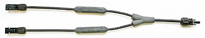
As compared to Option 1, the combination of leapfrog wiring and Y-connectors in Option 3 effectively reduces the homerun conductor length within the array by half. This setup does not offer a free lunch, however, as the cost to purchase Y-connectors and inline fuses offsets some of the PV Wire savings. While it is possible to purchase inline fuseholders and unfused Y-connectors separately and plug them together in the field, it is generally more cost-effective to purchase an integrated assembly. Companies such as Amphenol, Eaton, Shoals Technologies Group and SolarBOS all offer Y-connector assemblies with integral inline fuses. When purchasing an all-in-one solution, integrators should order extra assemblies for O&M purposes; in the rare event that one fuse blows, they will need to replace the entire assembly.
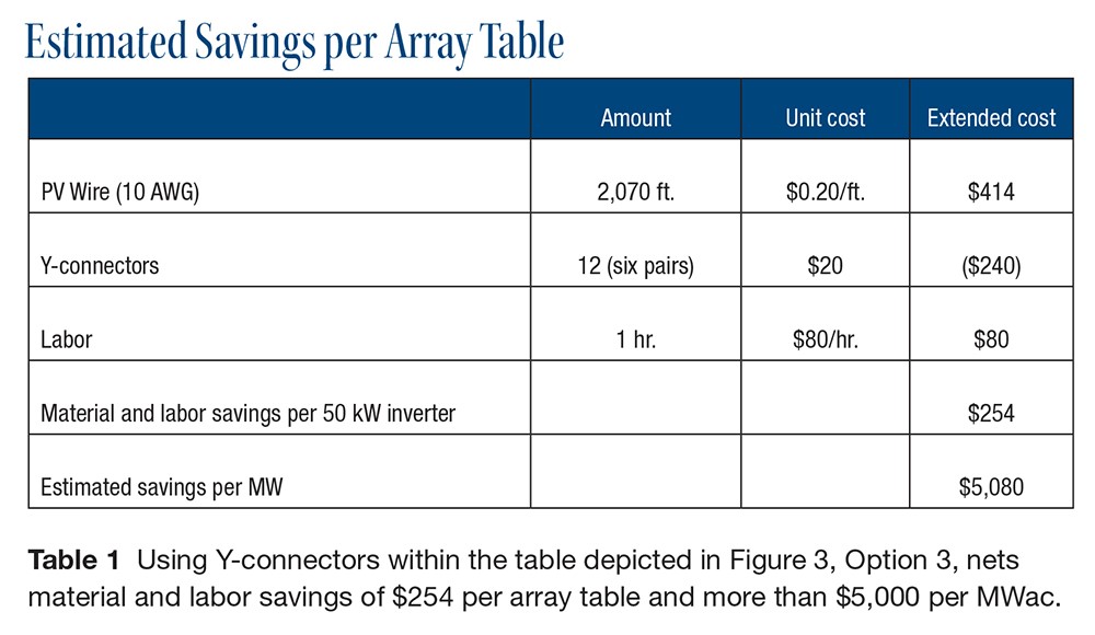
Table 1 estimates the total material and labor savings associated with deploying array-table configuration Option 3 rather than Option 1. Assuming that 10-gauge PV Wire costs $0.20/foot, you can save more than $400 per array table by adding Y-connectors at the end of each adjacent pair of source circuits (2,070 ft. × $0.20/ft.). While it will cost $240 to add six pairs of fused Y-connector assemblies (12 Y-connectors x $20/each), the net material savings per array table are roughly $174 ($414 less $240). Labor savings are estimated at 1 hour per array table and reflect the fact that installers will spend less time managing homerun conductors within the array (saving roughly 45 minutes) and will have to make only half as many dc terminations at the inverter (saving roughly 15 minutes). Assuming a labor rate of $80 per hour, the total material and labor savings are $254 per array table, which extrapolates to $5,080 per MWac ($0.005/W).
Of course, every array is different, and material and labor costs vary from region to region, so results may vary. However, this case study is a good example of the type of analysis that can help reduce costs, improve profits and win more projects. According to GTM Research, the utility-scale solar market in the US will approach 12 GW in 2016. If each one of these large-scale projects could reduce eBOS costs by a half cent per watt, the industry as a whole would save $60 million.
Questions or comments? Contact:
Eric Every
Sr. Applications Engineer
Yaskawa – Solectria Solar
eric.every@solectria.com
978-771-7598
Natalie Holtgrefe
Head of Marketing
Yaskawa – Solectria Solar
natalie.holtgrefe@solectria.com
781-640-0755
Please email questions and ideas to natalie.holtgrefe@solectria.com.